So what did I just do?
After installing the movement into a suitable enclosure, all three
hands will need to be manually aligned to 12:00, and then set to just
before
the approximate actual time.
The movement requires synchronization of the clock hand positions with
the receiver. The clock hands do not have an index position to locate
them
at a "known" value.
This hand synchronization is accomplished during a startup procedure
when you insert the battery. The instructions describe the sequence
when
to press the reset button.
After the battery has been installed, and the second hand has started
stepping along, the owner is instructed to press the reset button when
the second hand reaches 12:00.
Now, the second hand position is "known" relative to 12:00.
As the second hand passes over the minute hand, the owner is instructed
to press the reset button again.
And now the minute hand position is "known" relative to the second
hand position. Resulting in synchronization of the movement motor to
the
receiver/decoder circuit.
To indicate the receiver is "seeking" the signal; the seconds will
begin incrementing at what appears to be two steps every two
seconds.
Actually, the motor output is
sending a series of two pulses spaced by 250ms, and then waiting the
remainder of the two second period. Later returning to a 1pps output
when
the signal is acquired.
The shortfall with this design is that there's no automatic teaching
of the hour hand position; you must manually preset the hour hand
position
when installing a battery.
How does it work?
Two independent time bases are operating in the circuit. One (the WWVB
receiver/decoder), receives the time code information from a 60Khz AM
signal
via the ferrite
antenna, and that value is compared to the stored analog hand positions
taught at startup. The second time base is actually a simple quartz
clock
movement that can be
either accelerated or decelerated by the receiver/decoder circuit.
Note that the clock motor cannot be reversed; only decelerated until
the
actual time of day is achieved.
If the actual time of day is greater than 30 minutes from the minute
hand position, then the motor will be accelerated to synchronize to
it.
Likewise, if the actual time
of day is less than 30 minutes from the minute hand position, then
the motor will be decelerated until the actual time catches up to the
slowed
minute hand. Slick huh!
How can I use it in my Nixie Clock project?
If your Nixie Clock design is based on the customary 1pps signal from
a crystal or 60hz line frequency, you can use the WWVB radio
receiver
hack described here.
Implementation is very easy once you understand how the hand
synchronization
procedure works, and apply it to your clock circuit design. No special
tools needed!
Here's how we synchronize the receiver in a Nixie Clock
application:
First; a timer circuit is used to initiate a reset (mode sw) pulse
a few seconds after the power up of your Nixie Clock. Concurrently, a
separate
pulse is sent to reset
the seconds and minutes display of your Nixie Clock to zero.
The zeroing is the same sequence that tells the receiver/decoder that
both
hands are reset to 12:00:00.
Another timer begins, and waits for the first occurrence of the
one-minute
decade counter output being set. When the one-minute out becomes set,
the
MCU timer
program will pulse the mode sw high again. Again, the same
sequence that tells the receiver/decoder that the second hand has
reached
the minute hand's position.
A shortcoming of the nixie clock adaptation is the actual time could
be many minutes away from the reset to zero time, and may take up to 15
minutes after the signal
acquisition to synchronize the minutes display if the actual time is
slightly less than 30 minutes away from the displayed time, and the
clock
is slowed to synchronize.
The reset timer program was written for use in the Microchip 12C508A
MCU. This is a small 8 pin OTP MCU, and requires no
external
components for operation.
You're welcome to use the 12C508A program under condition that it is
not used for commercial purposes. Download the ready to program
WWVB.HEX
data here.
Click on the image below to view the detailed modification
procedure.
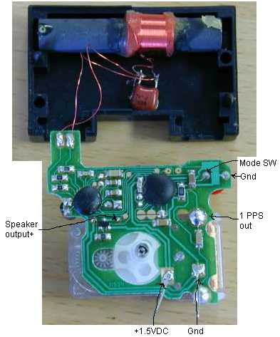
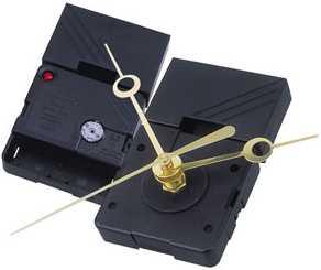
Figure 1
Figure 1 represents an image of the Quartex movement removed
from it's
enclosure. The antenna is shown in the cover, and the pcb has not
been modified.
The two large square pads (with short wires attached) are where the
power supply connections were made. The pad to the left in this view is
positive 1.5vdc.
1PPS signal out, is a TTL pulse used to drive the Nixie Clock. The
Mode SW is actually the reset input, with a simple transistor circuit
added
for buffering.
Click here
to view the modifications made to the Atomix (Quartex) Module PCB done
in a step by step sequence, providing nine images commented in detail.
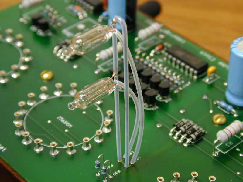
How do I make those interesting looking colon supports that
mount in
between the tube pairs? Click here
to download an image of the colon support.
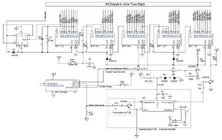
Example clock schematic with counter reset and 1pps inputs. Click on
the schematic image to download the example.pdf file.
The circuit schematic of the Nixie Clock shown above is
closely based
on an original design by Mike
Harrison.
I used much of the logic portion of Mike's clock circuit as
a Nixie clock example for the WWVB receiver hack.
Dual transformers are used for isolation purposes, and safe
construction.
A 9vac wall wart powers everything.
The Quartex receiver functions nicely from regulated
1.5vdc delivered
over a 120" phone wire. The clock circuitry powers the WWVB
receiver.
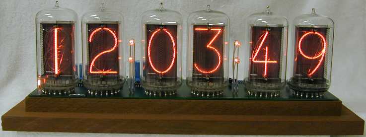
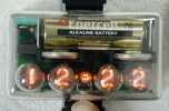
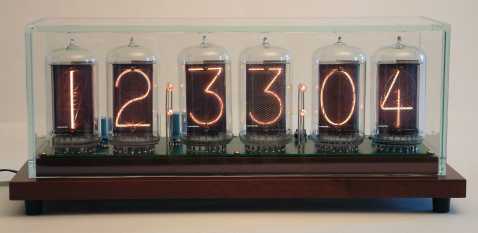
Here's an image showing my Radio Controlled clock after
assembly. It
was designed to use GIANT Z568M Nixie
Tubes
made in E. Germany.
The base is cut from two pieces of Walnut, then sandwiched to create
a stepped platform. I added a fitted clear acrylic cover for
protection.
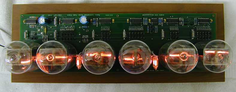
Another view looking down from above.
Overall clock error is less than 100ms from the WWVB clock
transmission.
This clock automatically adjusts for daylight savings time, and leap
seconds.
For an idea of it's size; the circuit board is 14 inches long, and
four inches deep. The Nixie tubes themselves stand four
inches
above the circuit board.
Are you fascinated yet?, see the world's
first Nixie
Tube Wristwatch. An amazing, humorous nixie creation in a field
of
it's own...
click on the image to visit the nixie clock and wristwatch
site.

