The Heath kit GC-1000 Most Accurate clock (well,
mostly anyway)
Power supply reliability upgrade information. Here's how
to do it, and it's pretty easy too!
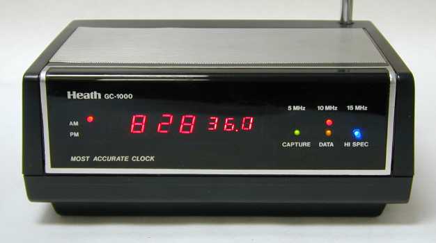
The Heathkit GC-1000 clock was the first consumer-grade digital clock
offering disciplined accuracy performance by means of radio reception.
We have one of these venerable old WWV clocks, and being 20+ years
old it was in need of some work to restore the clock to good operation.
I'm an EE, and I also dabble in designing and manufacturing GPS disciplined
Nixie Tube clocks as a side line hobby. Hoping to shortcut the time
spend under the cover of This Old Clock, I did a search on the internet
for published information about GC-1000 failures and common problems.
I came upon a couple of internet based businesses offering repairs and
upgrades for this clock, as well as a great article about accuracy
improvement.
Our clock really was not in need of a new
CPU board, or expensive tuneup work.
I already knew the problems were related to the power supply, even
though I could not find anything published about it. I did find that
the GC-1000 is certainly a beloved item from back in the glory days of
Heathkit Inc.
OK, I had some spare time, and it was time to have a look at the clock.
It certainly was dusty inside after opening it up for the first time in
20 years.
The clock always ran hot. And heat kills electrolytic capacitors. I
looked over the power supply section with a meter and scope. Really nasty
ripple.
Twenty years running in that heat had dried out the capacitors. Plus,
the ripple was very bad for that vintage CPU, and there's no cheap replacement.
In 1983, there were few choices for voltage regulation, and none of
them very efficient. Note the discoloring of the FR4 PCB material
in the power
supply section -too much heat for too long. I decided to replace the
vintage 7805 series regulator with an Integrated Switching Regulator module,
as well
as replace many of the electrolytic capacitors within the power supply
section. The new regulator would dramatically reduce the heat generated
from the
transformer and other related components in the power supply through
improved efficiency , as well as lower the overall power consumed by the
clock.
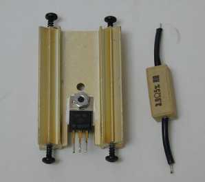
The voltage regulator U202 and it's heatsink were removed, and replaced
with a Power Trends (TI) PT5101 5V 1A Integrated Switching regulator.
I had to remove the test board that was originally mounted on top of
the regulator heat sink, and remount it with a stand off spacing it from
the board.
This PT5101N is currently available from DigiKey
for $12.25ea. The part shown on my example images will be different from
the part you receive.
Three 1000uf 25v radial Electrolytic capacitors on the main board required
replacement at locations C203, C205, and C206. One 330uf
25v radial
Electrolytic capacitor on the main board required replacement
at location C208. One 22uf 25v radial Electrolytic
capacitor at location C212 on the
main board (adjacent to the new regulator) required replacement,
and was upgraded to a 33uf 25v radial Tantalum capacitor for improved reliability.
A 3.9 ohm 5w resistor at location R201 was removed, and replaced by
an insulated jumper wire. Originally this was required to limit the incoming
voltage to the 7805 regulator, and is an unnecessary heat generator
with the new switching regulator installed in place of the vintage series
regulator.
Few other capacitors are involved with regulation, and I decided they
did not require replacement.
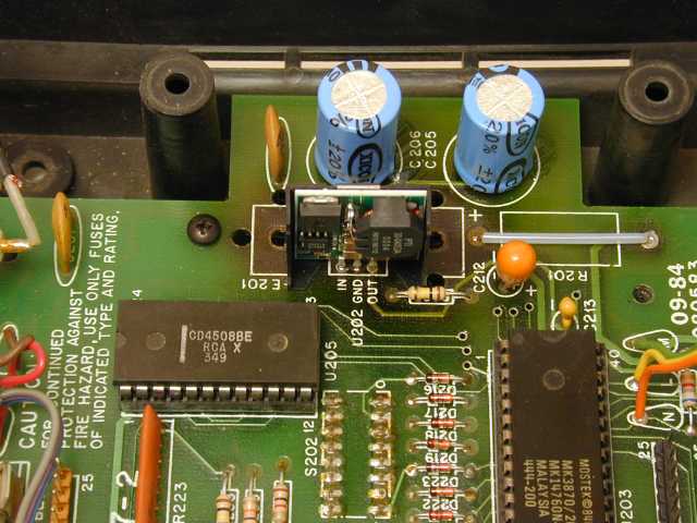
Image showing C205, C206, C212 and the new Integrated Switching Regulator
module already installed on the board.
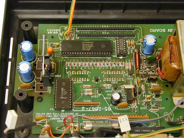
Image showing C203, C205, C206, C208, and C212. Note the toasty
FR4 board material at the voltage regulator and rectifier areas.
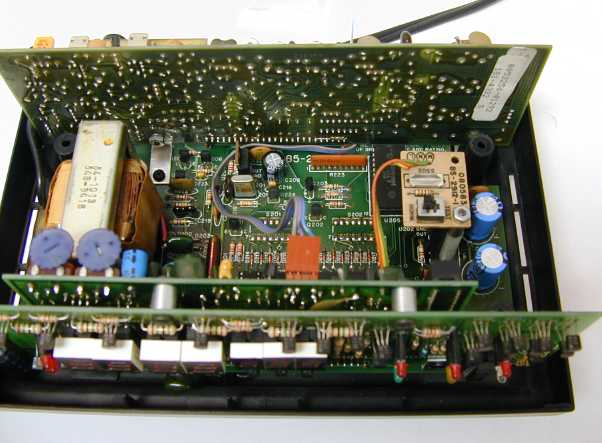
Image showing the GC-1000 reassembled, with a spacer installed to support
the test board over the new regulator module.
You will immediately discover the GC-1000 is operating cool, with barely
any detectable warmth from the clock cover.
I highly recommend completing the calibration procedure in the manual
after you have completed the power supply upgrade.
Update: April 2005
I recently noticed the fellow who offers the expensive GC-1000 tuneup
work has added a "cool clock" blurb to his web site.
Apparently this new blurb is in response to my posting of the GC-1000
information -enabling you to perform the PS reliability
upgrade work yourself at little or no cost. Don't be misled into purchasing
an aftermarket CPU, or other unneeded components.
The problem is simply an inefficient series regulator design and very
dried-out electrolytic capacitors. There are no cuts needed.
And no RF interference problems either. The information I have provided
is simple to understand, with no irreversible changes.
Update: June 2006
From all the email; the Heathkit GC-1000 Power Supply reliability upgrade
procedure has clearly been an outstanding success.
One expert in the GC-1000 field has been kind enough to share an image
the original GC-1000 program software running in the
Mostek MK3870 MCU. If you are lucky enough to own a piggyback ROM version
of that vintage MCU, you can program a
ROM with the object HEX data in this ZIP
file.
Jeff Thomas
Click
here to return to the Nixie Clock and Nixie Wristwatch site